
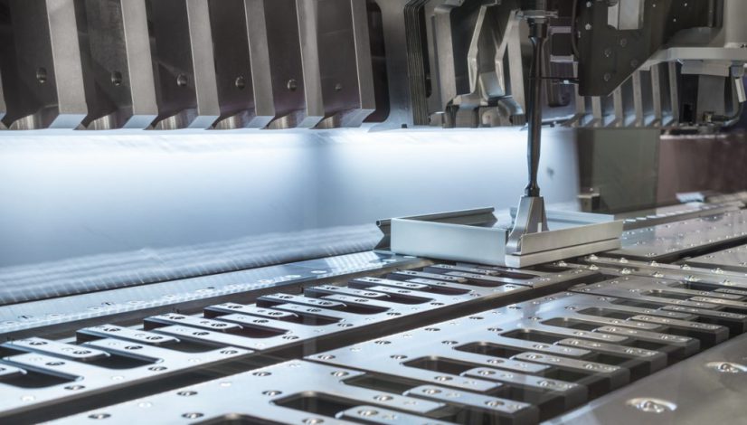
Achieving precise results in metal fabrication relies heavily on understanding the nuances of tool and die clearance in steel stamping. The gap between the punch and die, known as clearance, directly impacts part quality, tool life, and production efficiency. This steel stamping tool and die clearance guide provides a comprehensive look at the technical considerations, best practices, and troubleshooting tips for professionals and engineers working with steel stamping processes.
Proper clearance selection is essential for minimizing burrs, reducing tool wear, and ensuring clean sheared edges. Whether you are designing new tooling or optimizing existing operations, mastering clearance principles can lead to improved productivity and lower operational costs. For those interested in related topics, exploring how to optimize scrap chute angles can further enhance your stamping line’s efficiency.
Understanding Clearance in Steel Stamping
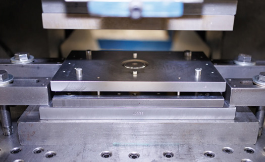
Clearance refers to the intentional space between the punch and die in a stamping tool set. This gap is critical for allowing the material to shear cleanly without excessive force or deformation. The right clearance depends on several factors, including material type, thickness, and the desired edge quality.
Inadequate or excessive clearance can lead to a range of issues, such as burr formation, poor edge quality, and even premature tool failure. By following a well-structured steel stamping tool and die clearance guide, manufacturers can achieve optimal results and extend the lifespan of their tooling.
Key Factors Influencing Tool and Die Clearance
Several variables must be considered when determining the ideal clearance for a stamping operation:
- Material Type: Harder materials like stainless steel require larger clearances compared to softer metals such as aluminum.
- Material Thickness: As thickness increases, so should the clearance to ensure proper shearing and to avoid excessive tool wear.
- Part Tolerance Requirements: Tight tolerances may necessitate smaller clearances, but this can increase burrs and tool stress.
- Tooling Material: The choice of punch and die materials affects how much clearance is needed for longevity and performance.
- Coatings and Surface Treatments: Stamping coated steels may require adjusted clearances to prevent damage to protective layers. For more on this, see best practices for stamping coated steels.
Calculating Optimal Clearance: Formulas and Standards
The most common method for determining clearance is as a percentage of material thickness. Industry standards typically recommend:
- For mild steel: 5% to 10% of material thickness per side
- For stainless steel: 10% to 15% of material thickness per side
- For aluminum: 3% to 7% of material thickness per side
For example, if stamping 1.0 mm thick mild steel, a clearance of 0.05 mm to 0.10 mm per side is generally suitable. However, always consult material supplier data sheets and perform trial runs to fine-tune these values for your specific application.
Effects of Improper Clearance
Incorrect clearance can cause several production issues. Too little clearance increases punching force, accelerates tool wear, and can result in cracked or rough edges. Too much clearance, on the other hand, may produce excessive burrs and poor part accuracy.
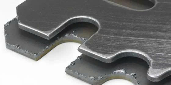
Burrs are a common sign of excessive clearance. These sharp edges can compromise part safety and require secondary deburring operations, increasing costs. Conversely, tight clearances can cause galling and premature tool breakage, especially in high-strength steels. For more on handling challenging materials, see steel stamping material yield strength considerations.
Best Practices for Setting and Maintaining Clearance
To ensure optimal results, consider these best practices:
- Regularly inspect punches and dies for wear and replace as needed.
- Use precision grinding and EDM processes to maintain consistent clearances.
- Document clearance settings for each material and thickness to standardize production.
- Monitor part quality and adjust clearance if burrs or edge defects appear.
- Utilize simulation software to predict and optimize clearance before tool fabrication.
Incorporating vacuum systems can also help with part ejection and reduce the risk of jams, especially in high-speed operations. Learn more about the benefits of vacuum systems in steel stamping for further improvements.
Advanced Considerations: Progressive Dies and High-Strength Steels
Progressive die setups and advanced high-strength steels (AHSS) introduce additional complexity. Progressive dies require uniform clearance across multiple stations to avoid cumulative errors. AHSS materials demand larger clearances and robust tooling to withstand higher forming forces.
For these applications, it’s crucial to collaborate with toolmakers and material suppliers to establish the right balance between clearance, tool life, and part quality. Ongoing process monitoring and data collection can help identify trends and prevent costly downtime.
Troubleshooting Common Issues in Steel Stamping
When defects occur, use the following troubleshooting tips:
- Excessive Burrs: Increase clearance incrementally and check for improvement.
- Cracked Edges: Reduce clearance or check for tool misalignment.
- Rapid Tool Wear: Confirm clearance is not too tight and ensure proper lubrication.
- Poor Part Ejection: Consider optimizing part ejection strategies, such as those outlined in how to optimize part ejection in stamping.
If persistent problems arise, consult with experienced die designers or reference technical resources such as the MCR Safety metal stamping blog for additional troubleshooting advice.
Frequently Asked Questions
What is the recommended clearance for mild steel in stamping operations?
For mild steel, the typical clearance is 5% to 10% of the material thickness per side. This range offers a good balance between edge quality and tool life, but adjustments may be needed based on part requirements and tool condition.
How does improper clearance affect stamped part quality?
Incorrect clearance can lead to burrs, cracked edges, dimensional inaccuracies, and increased tool wear. Ensuring the correct gap between punch and die is essential for producing clean, accurate parts and minimizing secondary operations.
Can clearance settings be standardized across different materials?
While general guidelines exist, clearance should be tailored to each material type and thickness. Harder or thicker materials typically require larger clearances, while softer or thinner materials can use tighter gaps. Always verify with test runs and adjust as needed.
Conclusion
Mastering the principles outlined in this steel stamping tool and die clearance guide is essential for achieving high-quality, cost-effective results in metal stamping operations. By understanding the factors that influence clearance, following industry best practices, and staying vigilant with process monitoring, manufacturers can optimize both part quality and tool longevity. For further insights into related aspects of steel stamping, explore the internal resources linked throughout this article.